
Foreword
In the previous article, the author introduced the first case of built-up edge. Combined with the actual case, the influence of blank allowance, equipment rigidity and coolant characteristics on the built-up edge was analyzed.
In this article, the author will introduce the fourth factor that affects the generation of built-up edge: cutting parameters. Stop gossip, turn into a detective, and go to the scene!
1. Traces on the steel sleeve
The working condition of this case is to use PCD guide bar boring tool to finish machining the steel sleeve. Readers who have forgotten what a guide bar boring tool is, please refer to the previous article "How to Correctly Use a PCD Guide Bar Boring Tool".
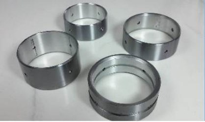
The steel bushing here is actually a composite bushing. The outer layer is aluminum and the inner layer is steel. First, it is press-fitted to the parent workpiece (aluminum part) by an interference fit, and the bushing hole is roughed. , followed by finishing to form a mating contact surface that is tightly integrated with the parent body (outer aluminum) and wear-resistant (inner steel).
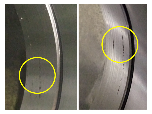
On the day of the crime, some scratches suddenly appeared discontinuously on the finished steel sleeve, as shown in the figure below.
2. Appearance characteristics
The detective first observed these scratches, and concluded the following characteristics: in the feeding direction, they are concentrated in the middle position, and there is no obvious entrance concentration; the circumferential direction shows intermittent linearity, with a small slope and a short length. , less than 1/4 turn.
This feature is obviously different from the scratches caused by the secondary extrusion of chips (refer to the previous article "Influence of Residual Chips in the Workpiece and Its Elimination and Discharge Method"), and it does not conform to the appearance characteristics of the retraction pattern and large slope, and even the same as the previous issue. The mentioned reamer built-up edge scratches also differ in appearance.
3. Component analysis
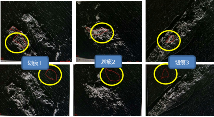
Subsequently, the probe conducted elemental composition analysis on the scratch position and its nearby normal position, as shown in the figure above, and compared them.
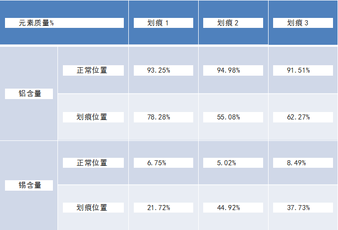
The results are shown in the table above. This probe found that the tin content in the scratched position was higher than that in the normal position. This leaves two possibilities:
The first possibility is that the composition of the steel sleeve is unevenly distributed, and that "agglomerated tin lumps" are produced in certain locations. These "tin agglomerations" happen to appear at the depth of the machined surface and are exposed by the cutting edge. As shown below:
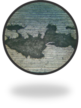
This is an intuitive idea, but it does not follow a statistical distribution: if the "tin agglomeration" is randomly distributed in the steel jacket material, why is it concentrated in the middle? Why is there an intermittent linear distribution?
The second possibility is that these tin elements were originally distributed evenly in the workpiece material with a low content, and under the promotion of some action, they were first concentrated and then left on the machined surface of the workpiece.
In this way, the latter question arises, what is the role that promotes the concentration and residue of tin elements. To explain this problem, we want to expand to the role of the element tin in steel.
4. Innocent Tin
Free-cutting steel with high cutting performance in the traditional sense, which contains lead. However, lead free-cutting steel is contaminated with lead in the production and use process, and its application is limited. Some downstream industries in Europe and the United States have banned the use of lead free-cutting steel. Therefore, the industry is exploring lead-free free-cutting steel.
At this time, the tin element made a grand debut.
In 1999, USS/KOBE produced the world's first heat of tin free-cutting steel, which researchers at the University of Pittsburgh called "green steel."
Tin is non-toxic and is a very environmentally friendly element. In the periodic table of elements, tin and lead belong to the same family and have similar physical and chemical properties. The melting point of tin is lower than that of lead, at 232 °C.
In general, the added low-melting free-cutting elements mainly improve the cutting performance of the material through the following aspects:
Lubrication: When the temperature during cutting reaches above the melting point of the free-cutting element, the free-cutting element in the molten state becomes the lubricant between the cutting tool, the chip and the workpiece interface, which can reduce frictional resistance.
Brittleness of molten metal: Same as lubrication, when the temperature rises during cutting, the free-cutting element in the molten state reduces the bonding force of the interface atoms, thereby catalyzing the metal and improving the breakage of the chip.
Stress concentration source: The stress concentration source is generated in the shearing area of the cutting process, which can induce small internal cracks to reduce cutting resistance and improve chip breakage.
In addition, some free-cutting primary colors, such as Pb, Bi, etc., are easy to nucleate and grow on the free-cutting phase of plastic inclusions of MnS. The MnS interface preferentially initiates and expands, which is easy to break chips during material cutting and obtains a better surface finish.
In summary, the improvement of its cutting performance is mainly due to the brittleness effect of the molten metal of the low melting point metal tin, and the stress concentration source caused by the segregation of tin at the grain boundary, that is, the MnS interface. (Quoted from Zhang Yongjun et al. "Research on the Effect of Tin on Improving the Cutting Performance of Materials").
5. The real murderer behind the scenes
From the above we can see that tin element exists in steel, mainly to improve the cutting performance of the material. Because of its low melting point, only 232 °C, it is easy to precipitate in a molten state and accumulate on the tip of the blade.
But what is there on the tip of the knife that can enrich the tin element?
Although there are still many people leaving messages saying that the friction coefficient of PCD tools is small and there will be no built-up edge, but as shown in the figure below, this probe has at least seen the chip build-up on the cutting edge. These built-up chips are created, grown, and shed during the cutting process. Can't they be a built-up edge?
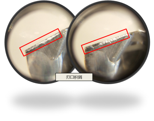
Returning to the case, the appearance of the tin element accidentally exposed the existence of the built-up edge: the low-melting tin element is enriched in the built-up edge of the tool tip, the built-up edge falls off, scratches the machined surface, and the tin element also With left on the workpiece surface.
In order to verify the inference of this probe about built-up edge, this probe increased the cutting parameters by 50%, intending to avoid the speed range generated by the built-up edge. As a result, after the parameters were adjusted, the scratches disappeared immediately, and the problem was successfully solved.
【Conclusion】
There have been many readers and friends who have left messages to discuss whether the built-up edge exists in the working conditions of PCD tools for processing aluminum parts. Through the three articles on the topic of "Built Bump", you must have come to your own conclusion.
The purpose of the discussion is to solve the problem. I hope you can apply the solutions of these two cases to your own work, and you will not waste the author's writing of thousands of words.