
In previous articles, when the author introduced the PCBN tool, he mentioned that the chamfering is the lifeblood of the PCBN tool. The chamfered edge that matches the machining conditions can greatly improve the tool life and the stability of machining quality.
At present, there are many researches on PCBN tool chamfering at home and abroad, but the mathematical model between cutting parameters and PCBN tool material has not been established. Therefore, in practice, groping methods are often used.
There are two key index parameters in chamfering design: chamfering angle and chamfering width. The author first selected a journal paper that introduced the effect of different chamfering parameters on cutting force and tool life, using PCBN inserts for interrupted cutting of hardened steel.
1. Test background
Due to the advantages of high hardness, good thermal hardness and high chemical inertness, cubic boron nitride (PCBN) tools are widely used in dry, hard, high-speed continuous cutting of difficult-to-machine materials such as ferrous metals and superalloys. , so that the cutting efficiency and processing quality have been greatly improved.
However, due to the high brittleness of PCBN tools, they have not been popularized in interrupted cutting machining, and the selection of tool geometric parameters and material types is in a blind state. Therefore, it is imperative to study the cutting performance of interrupted machining PCBN tools.
At present, foreign researchers' research content on PCBN tool intermittent machining quenching hardware mainly focuses on tool wear, while domestic research is still in its infancy.
Because PCBN tools usually use negative chamfering, and the geometric parameters of negative chamfering have a great influence on the cutting performance of PCBN tools, this paper qualitatively and quantitatively studies the effect of negative chamfering angle on cutting force during interrupted cutting. and tool life, the results have a guiding role in production practice.
2. Test conditions
1. Test equipment
The cutting test was carried out on a CA6140 machine tool. The cutting force was measured with a KISTLR dynamometer produced in Sweden, and the microscopic wear morphology and micro-area composition of the tool flank were observed and analyzed with a JSM-6360LV scanning electron microscope. The tool flank wear was measured with an ordinary tool microscope.
2. Test tool
The PCBN material adopts the BN250 composite sheet produced by Sumitomo Corporation of Japan, which is a blade with low CBN content. The specific parameters are shown in Table 1 below.

Table 1-BN250 mechanical properties and chemical composition
The negative chamfering angle of the tool is -15°, -20°, -25°, -28° respectively (the negative chamfering angle is usually a negative value, and the negative sign is omitted in the following description), and the chamfering width is 0.2mm. The remaining angles of the tool are shown in Table 2 below.

Table 2 - Tool geometry angles
The workpiece material is GCr15 (60-62HRC), and its chemical composition is shown in Table 3 below.
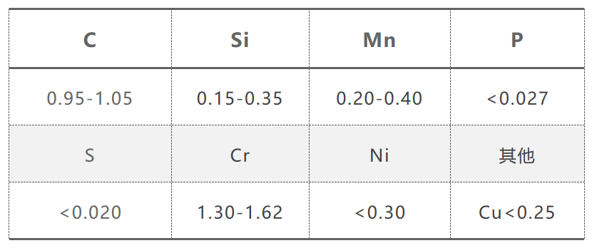
Table 3 - Chemical composition of GCr15
In order to simulate intermittent cutting, the author made grooves on the surface of the workpiece. The schematic diagram of the workpiece is shown in Figure 1 below.
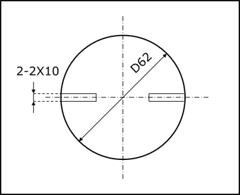
Figure 1 - Grooving in the surface of a shaft-shaped workpiece to simulate interrupted cuts
3. Test data
1. Test data - cutting force
There are cutting periods and empty periods in the interrupted cutting process.
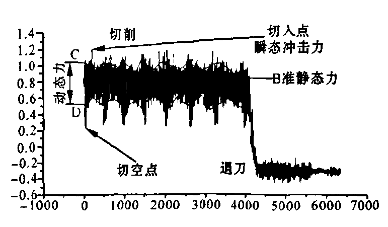
Figure 2 above is the cutting force signal curve during intermittent cutting. The area between the two polylines C and D in the figure corresponds to the dynamic cutting force signal, the straight line B corresponds to the quasi-static force signal during the cutting period, and the two polylines C and D correspond to the dynamic cutting force signal. The outside peaks and troughs correspond to the cut-in point and the cut-out point respectively, and the signal corresponding to the cut-in point is the transient impact signal.
The variation curves of quasi-static force and transient impact force with negative chamfering angle are shown in Figure 3 below.
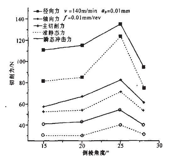
Figure 3 - Variation curve of quasi-static force and transient impact force with negative chamfering angle
2. Test data - tool wear
In the process of interrupted cutting, when PCBN tools are used for continuous cutting, VBmax=0.2mm is used as the blunting standard. Considering the large impact of interrupted cutting on the tool, this paper adopts VBmax=0.3mm or cutting edge chipping as the blunting standard. .
There are cutting periods and empty periods.
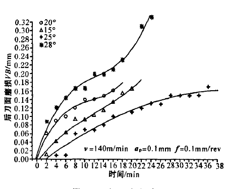
Figure 4 - Tool life graph
The tool life curve is shown in the figure above and the tool life curve graph. The tool life is shorter when the chamfering degree is 15° and 20°. The latter has a small chipping when the cutting time is 2min, which accelerates the tool wear, but does not Affecting the processing effect, when the cumulative cutting time reaches 20min and 14min, both knives appear chipping phenomenon.
The tools with chamfering degrees of 25° and 28° did not appear micro-chipping in the early stage of cutting, and the tools entered the normal wear stage. The cumulative cutting time of the two tools was 36min and 24min respectively.
[Article summary] Due to space limitations, the author temporarily closed the paper after showing the cutting force and tool wear test data obtained from the test. I also hope that readers can observe the characteristics of the experimental data for themselves.
In the next article, the author will lead readers to analyze the experimental data and explore "why the radial force is greater than the axial force and the tangential force".