
1
Lathes & Milling Machines

Turn-broaching machine is a special processing equipment for shaft products such as crankshafts. It is mainly used for the finishing of journal surfaces, grooves and their end faces.
Milling machines are often used to rough and finish the surface of shaft parts.
In the crankshaft machining process, the main journal (the axis of rotation coincides with the axis of the part) and the connecting rod journal (the axis of rotation is parallel to the axis of the part) are usually milled and roughed by a milling machine, and the blank allowance is removed, and then the lathe and broaching machine are used respectively. The milling machine finishes the main journal and the connecting rod journal.
Since the axis of rotation of the connecting rod does not coincide with the axis of rotation of the part, the helical interpolation milling is used when milling the connecting rod.
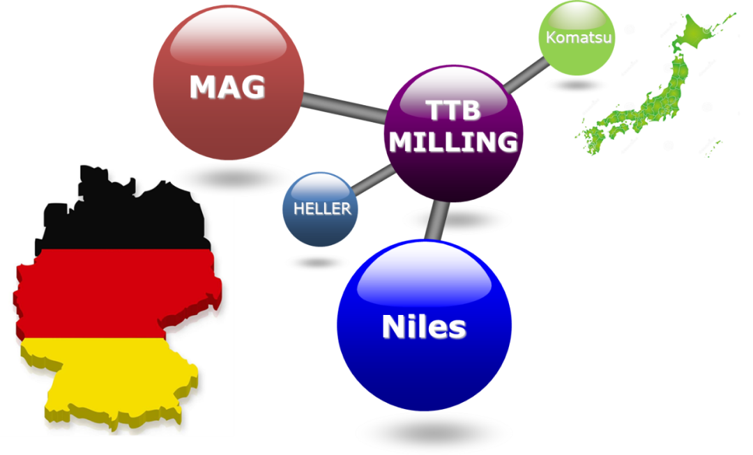
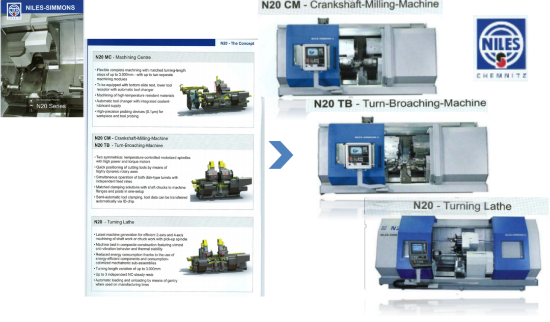
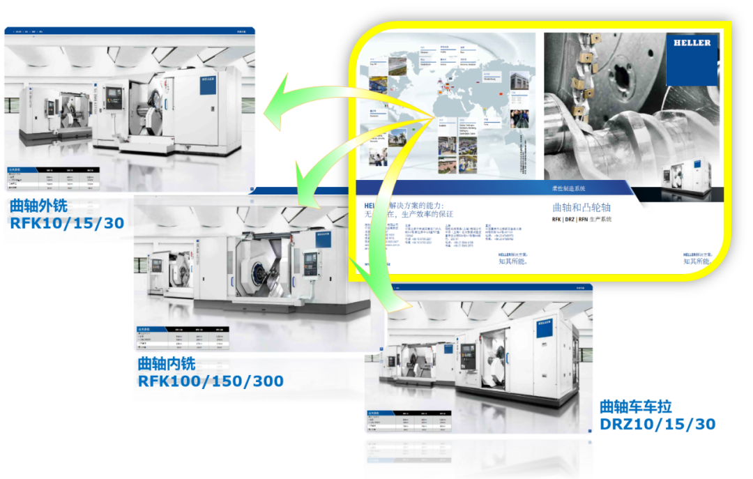
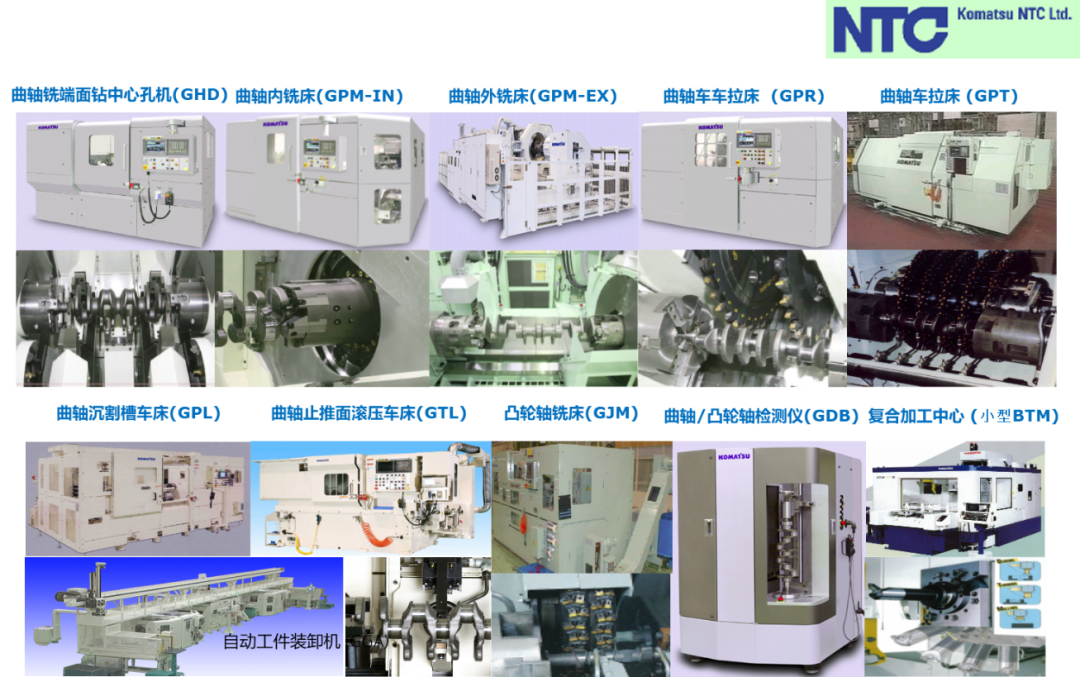
1.1 Common equipment brands
1.2 Common tool types
The lathes and milling machines of the crankshaft automated production line usually take the form of cutter heads and turrets.
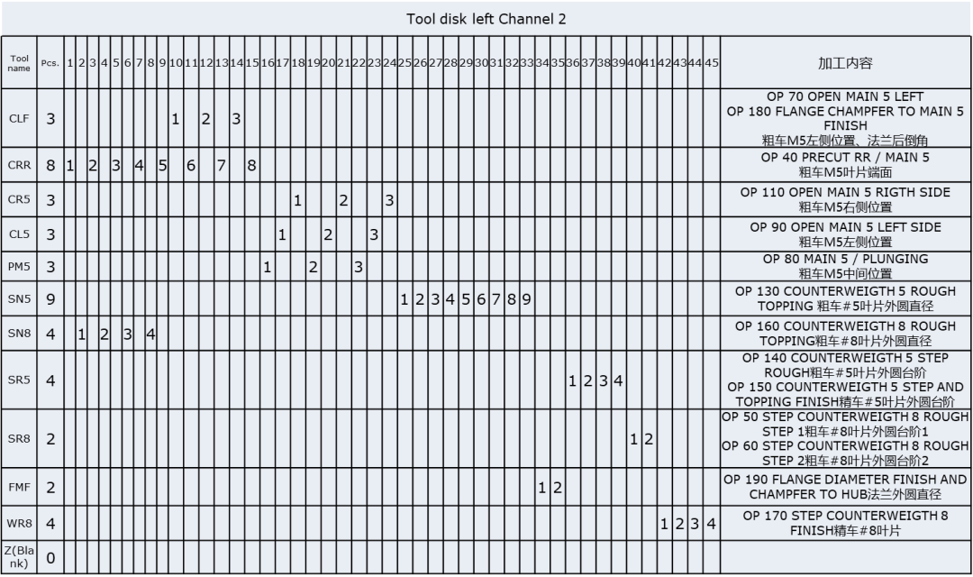
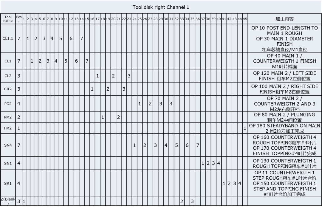
There are a total of 45 tool positions in the turning and broaching cutter head, and a blade is arranged on each cutter position. During processing, the cutter position is changed according to the programmed rotation to realize automatic tool change and processing.
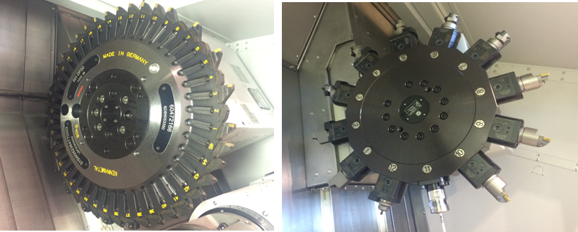
The figure below shows the arrangement of the blades on the cutter head of the turning equipment, which is used to quickly confirm the life of the tool and the status of the specific blade.
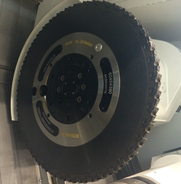
The same inserts are arranged on the circumference of the milling cutter head, the cutter head rotates at high speed during machining, and the cutting allowance of each insert is the same.
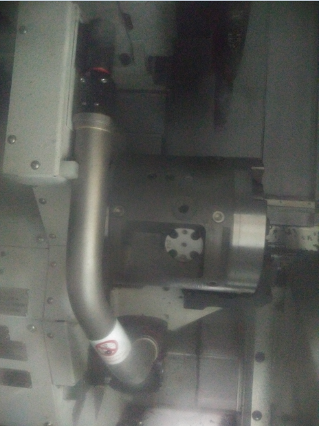
Automatic tool setting function: For turning and finishing machine tools, it is equipped with a tool setting instrument, which can automatically set the tool after each tool change, which can automatically and accurately obtain the tool size and improve the machining dimensional accuracy.
1.3 Processing content
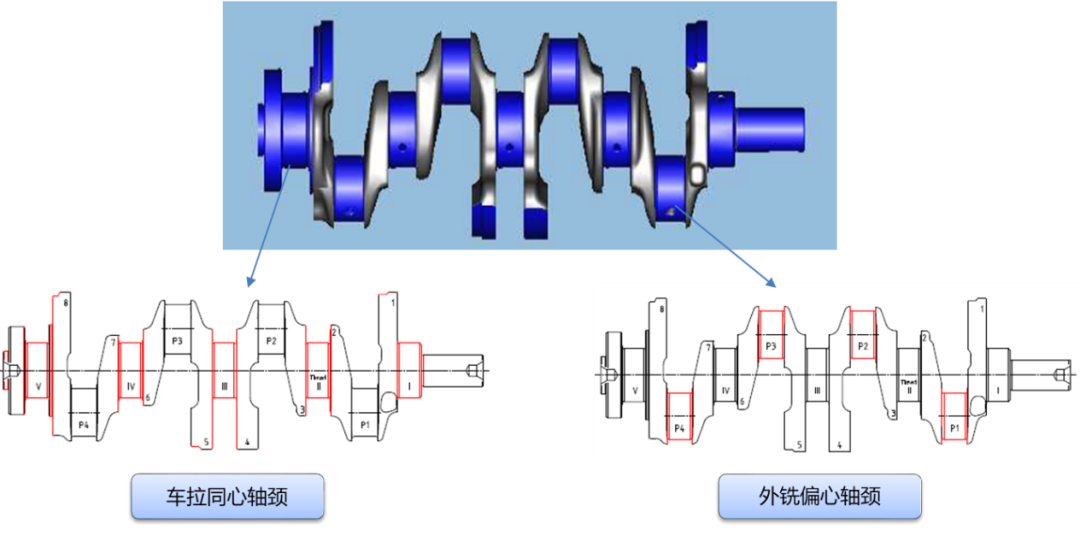
Processing content: Turning concentric journals, external milling of eccentric journals & concentric journals
1.4 The positioning and clamping method of the cart

Pre-support: mandrel, outer circle of large oil seal, the form of bracket can be divided into: fixed V-block, retractable bracket.
Positioning: center hole at both ends, cone center (surface contact), ball center (line contact), limited to 5 degrees of freedom.
Clamping: Clamp the mandrel and the outer circle of the large oil seal to drive the workpiece to rotate at high speed.
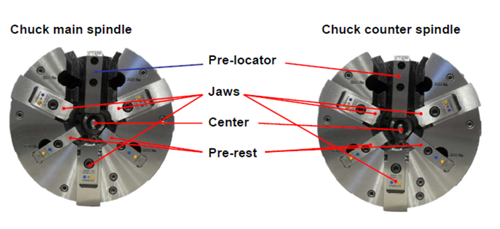
It is worth noting that the realization of the above functions all rely on the design of the left and right chucks, as shown in the following figure:
1.5 Processing content

Pre-support: Main1, the outer circle of the large oil seal, the form of the bracket: integrated into the head and tail frame chuck.
Positioning: The center hole at both ends limits 5 degrees of freedom; the Pad surface or the outer circle of Pin1 limits the degrees of freedom of angular rotation of the workpiece.
Clamping: Clamp Main1, the outer circle of the large oil seal to drive the workpiece to rotate
Correspondingly, the chuck of the external milling equipment is shown in the following figure:
1.6 Processing problems and countermeasures
Left and right cutter heads are wrongly installed:
Mechanical error proofing is performed by setting error-proof pins on the cutter head mounting surface to cooperate with the cutter head holes.

Crash problem
Mainly occurs in the rough turning insert of the turning machine, and the monitoring method adopts Artis 100% monitoring of the spindle load.
The main operations of Artis:
(1) Optimize the monitoring line
(2) After the alarm, clear the alarm and continue processing
Vibration problem
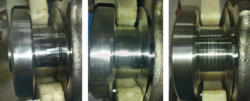
When the turning equipment starts to be debugged, there is a serious knife pattern on the main journal, and the center height / blade clearance angle / feed speed will all affect this problem.
Improvement measures:
(1) Improve the surface quality by adjusting the center height/intermediate roughing allowance/cutting feed rate.
(2) By changing the process, the broaching process is increased.
(3) The surface problem is solved, but it is necessary to pay attention to the cutting edge of the insert at this position.
2 heat treatment
2.1 Purpose of heat treatment
Heat treatment is to heat the metal workpiece to a suitable temperature in a certain medium, and after maintaining this temperature for a certain period of time, it is cooled in different medium at different speeds, by changing the surface or internal microstructure of the metal material. A process in which structures are used to control their properties.
(1) Appropriate metal heat treatment process can eliminate various defects caused by hot working processes such as casting, welding, and forging, refine grains, eliminate segregation, reduce internal stress, and make the structure and properties of steel more uniform.
(2) Change the internal structure of steel to improve its performance.
(3) The surface of the workpiece can have special physical and chemical properties such as wear resistance and corrosion resistance through metal heat treatment.
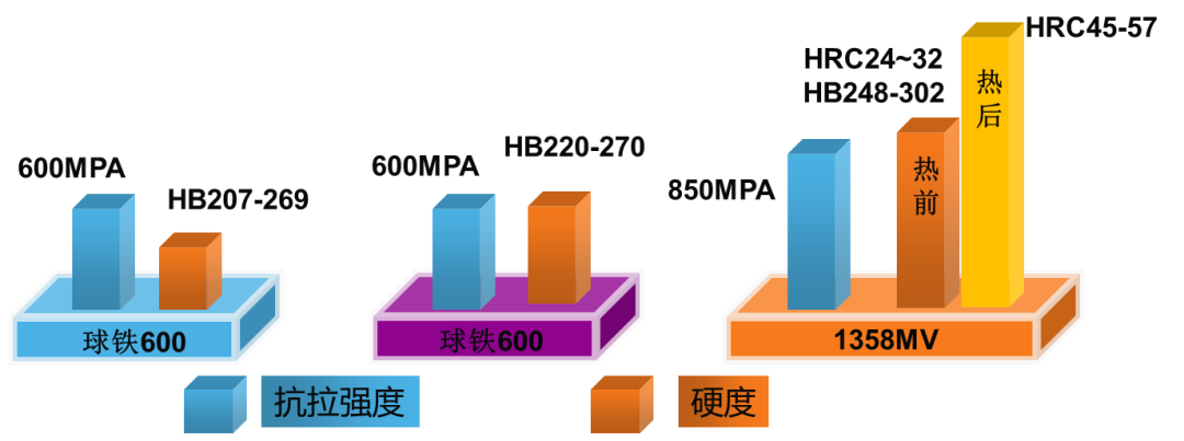
The following figure shows the material properties of crankshafts of different materials after heat treatment:
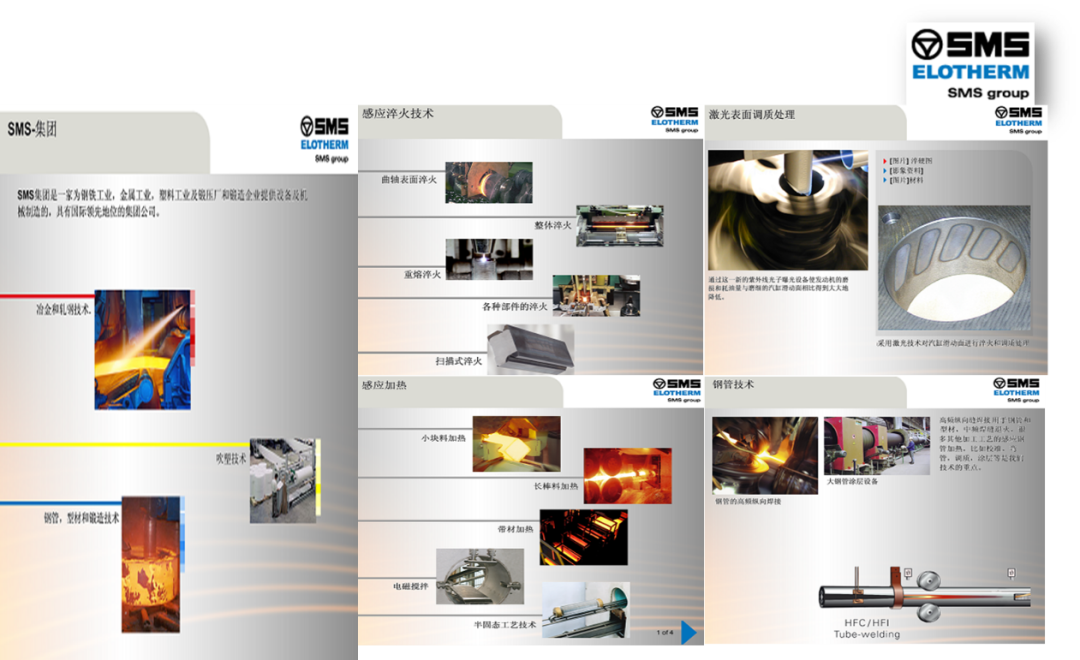
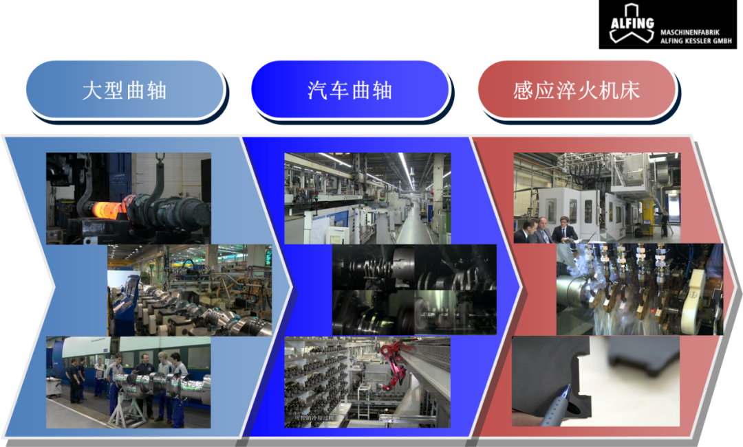
2.2 Common equipment brands

2.3 Heat treatment process
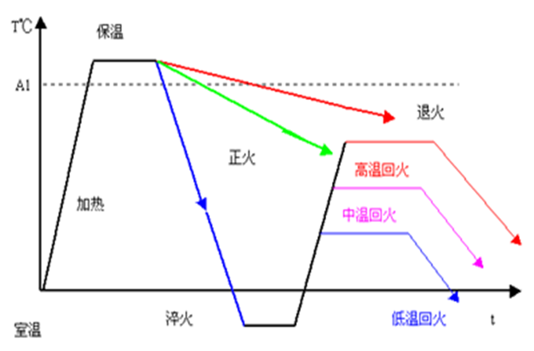
Common heat treatments, as shown in the figure below, heat the metal to A1 temperature, with different cooling problems and rates.
2.4 Heat treatment process of steel crankshaft
Processing content: main journal, connecting rod journal quenching + tempering
Positioning benchmark: front and rear top

work process:

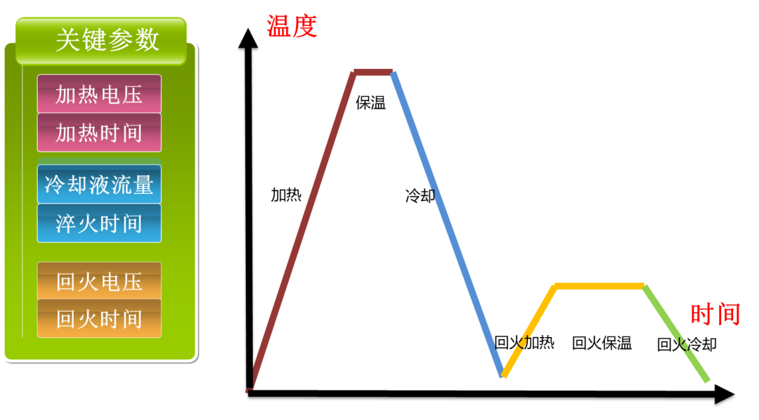
2.5 Heat treatment parameters
The key parameters of heat treatment are shown in the following table:
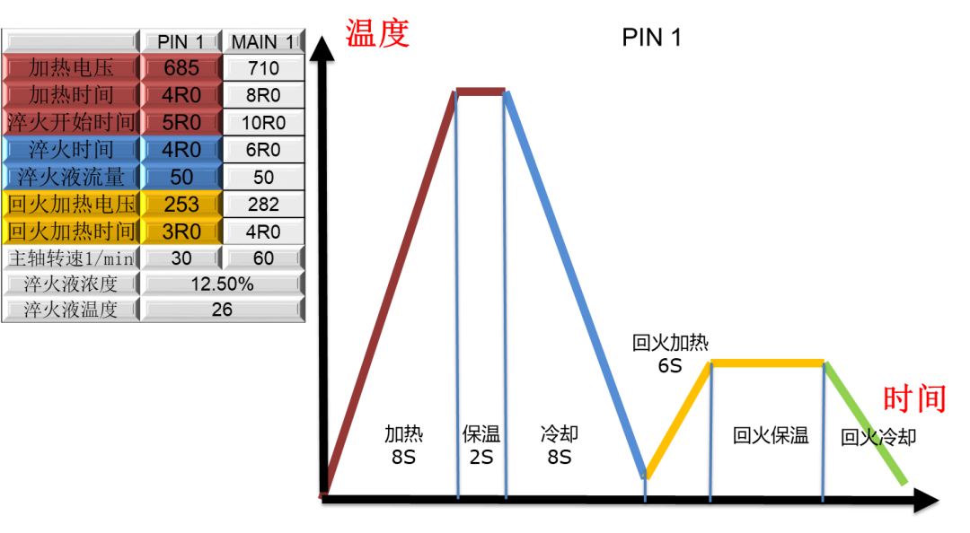
Practical case: heat treatment parameters of connecting rod journal and its process curve.
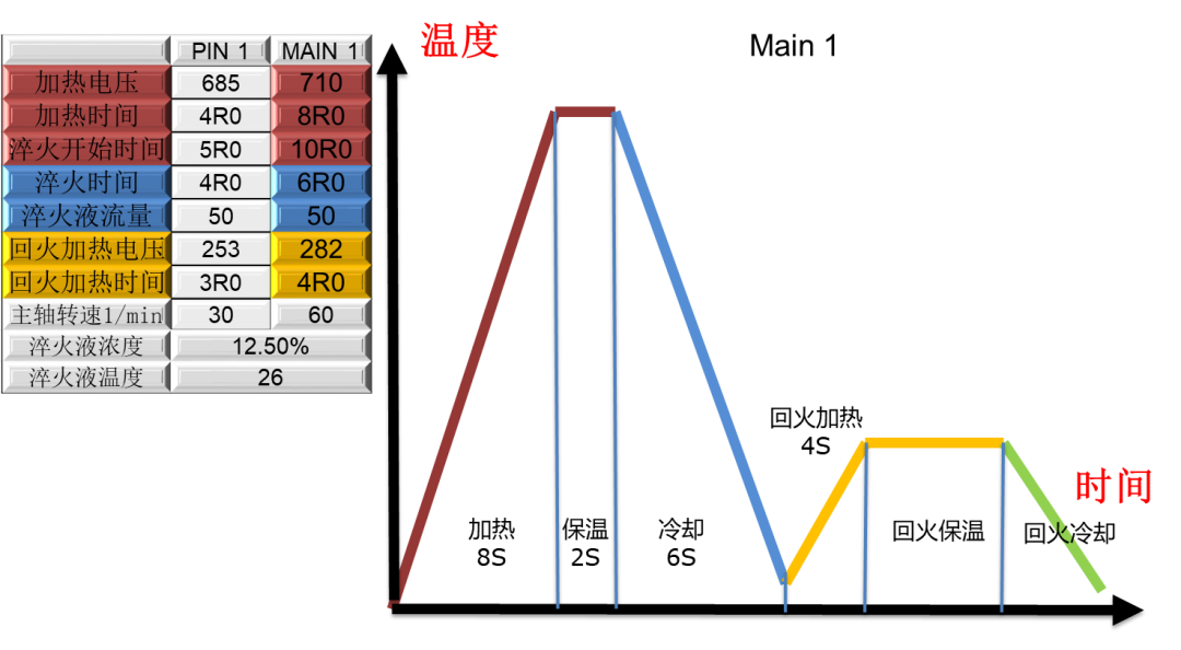
Practical case: main journal heat treatment parameters and their process curves.
The influence of heat treatment parameters on the heat treatment effect, as shown in the table below, is full of dry goods.
