Foreword
The previous article introduced the tool selection, tool installation and programming among the five factors that affect the quality of thread machining. This article continues to introduce the remaining two factors:
Factor 4: Feed method and coolant.
Reasonable feeding method and process design
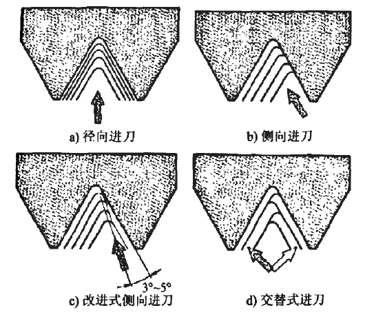
On CNC lathes, there are four common feed methods for thread processing: radial feed, side feed, improved side feed and alternate feed, as shown in Figure 1. Whether the feed method is reasonable or not directly affects the machining quality of the workpiece and the service life of the tool.

1. Radial feed method
Radial infeed is the most commonly used traditional infeed method and is the only method available on many machine tools, as shown in Figure 1a.
The cutting method is that the blade is directly fed into the workpiece, the formed chips are relatively hard, and the two edges work at the same time, the cutting force is large and the chip removal is difficult, so the two cutting edges are easy to wear during cutting.
When cutting a thread with a larger pitch, due to the larger cutting depth, the blade wears faster, resulting in a pitch diameter error of the thread, but the machining accuracy of the tooth shape is higher, so it is generally used for small pitch threads and hardened materials ( Such as austenitic stainless steel) processing.
The thread programming command G92 adopts the radial infeed method. Since the tool movement and cutting are all done by programming, the machining program is long and the cutting edge is easy to wear, so it is necessary to measure and compensate frequently during machining.
2. Side feed method
The lateral feed method reduces the bending pressure on the cutting edge, and the cutting state is stable, as shown in Figure 1b.
Since the side-feed cutting method is single-side cutting, the cutting edge is easy to be damaged and worn, so that the processed thread surface is not straight, and the tip angle changes, resulting in poor tooth shape accuracy. However, because it is a single-side edge operation, the tool load is small, the chip removal is easy, and the cutting depth is decreasing, so this processing method is generally suitable for large-pitch thread processing.
Because the chip removal is easy and the cutting edge processing conditions are better, this processing method is more convenient when the thread accuracy requirements are not high.
3. Improved side feed method
The improved side feed method is the most suitable processing method for CNC machine tools, and the side feed can be realized by programming.
For example, the feed method of G76 command in FANUC CNC system is this type. As shown in Figure 1c, the insert is fed with a profile angle smaller than the clearance angle. For example, for thread cutting with a profile angle of 60°, the axial feed can simply be calculated as 0.5 times the radial feed.
For a 55° profile angle, it should be calculated with a radial feed amount of 0.42 times, so that a feed angle that is 5° smaller than the thread profile angle can be obtained.
As a result, less heat is generated on the tool tip, which reduces vibration when machining coarse threads or when contact lengths are long.
4. Alternate feed method
As shown in Figure 1d, alternating infeed cuts one side of the thread profile in several increments, then the other side, and so on until the entire profile is cut. Since the cutting edges on both sides are used equally, the blade wears evenly, which increases the service life of the tool. Alternate feed is mainly used for large pitch thread cutting, but requires specific programming on CNC machine tools.
factor 5
Choose the right cutting fluid
When turning threads, the proper use of cutting fluid can reduce the heat generated during cutting, reduce the machining error caused by temperature rise, form a film on the metal surface, reduce the friction between the tool and the workpiece, and flush away the chips in time, thereby Reduce workpiece surface roughness value and reduce tool wear.
According to the test, it is sufficient to use water-based cutting fluid to process the general requirements of the thread; if the thread requires high precision, oil-based cutting fluid, such as kerosene, vegetable oil, etc., must be used.
The cutting fluid tank for turning generally contains water-based cutting fluid, so when machining threads, manual lubrication with an oil gun can meet the accuracy requirements.
Case explanation
The radial feed method is the most common cutting method, but its disadvantage is that the force on the blade is uneven during cutting, and it is easy to vibrate the tool.
With the increase of the amount of back-engagement, the cutting area gradually increases. When the tool tip is close to the large diameter of the thread, the tool has the greatest resistance.
At this time, if the rigidity of the tool, workpiece and machine tool is not good, it is easy to cause resonance when the workpiece is cut, which affects the surface roughness of the thread. Although reducing the amount of knife back can alleviate vibration, it will affect production efficiency.
To efficiently process large-pitch and large-size internal threads away from the end face, the rigidity requirements of the tool, workpiece and machine tool must be met at the same time. The tooth shapes of various threads are different from each other, and the corresponding processing procedures are also different. If the general method is used for programming, it needs to be written sentence by sentence.
The general program for large-pitch threads provided below uses the calculation and cycle functions of the numerical control system to control the cutter to cut multiple cutters in the transverse and radial directions of the thread, which greatly reduces the cutting resistance and can be used without changing the rigidity of the hardware. , Through the change of cutting method, the processing of various types of threads can be completed.
Take the use of forming inserts, the material to be processed is 42CrMo, the hardness of quenching and tempering is HB230, and the serrated thread is processed by CNC lathe as an example.
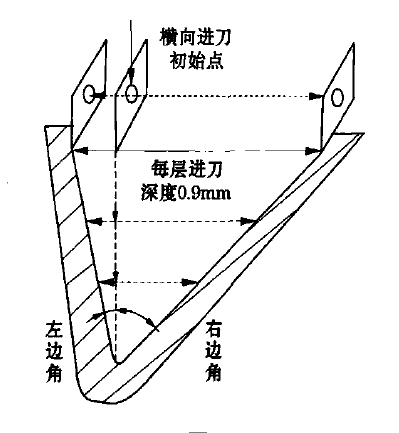
The thread adopts layered infeed along the diameter direction (ie x-axis), and the depth of each layer is 0.9mm; along the length direction (ie, z-axis), the thread is fed alternately, offset from the center line of the root arc to the left and right sides , Approaching with a small straight line, it is necessary to calculate the starting point position of the transverse tool and the number of tool feeds for each cutting.
Other types of threads are usually offset to the left and right sides with the midpoint of the tooth width as the centerline. The figure below shows the toolpath map for roughing.

(1) Determination of the number of passes in the transverse direction (z-axis)
The number of transverse passes = the number of infeeds from the initial point of transverse infeed to the left + the number of infeeds from the initial point of transverse infeed to the right.
The initial point of transverse infeed is the number of infeeds to the left = [(tooth profile height - finishing amount) - number of radial infeeds × each radial infeed amount] × TAN (left corner) / each lateral infeed value .
The number of infeeds to the right from the initial point of transverse infeed = [(profile height - finishing amount) - times of radial infeed × radial infeed amount per time] × TAN (right corner) / transverse infeed value per time .
(2) Processing steps
1. The z-axis is positioned to the initial point of lateral infeed bounded by the center of the tooth bottom arc, and the x-axis is positioned to the infeed depth of the first layer.
2. Carry out the thread processing of the pitch P, after the completion, the z-axis returns to the initial point of infeed.
3. The x-axis is still positioned to the infeed depth under the current layer, and the tool is shifted to the left along the z-axis to the starting point of the next threading process. Repeat steps ② and ③ until the thread centerline is at the left profile at the radial value. Contour forming.
4. The radial coordinate is unchanged, the tool is offset to the right along the z-axis by a certain distance, and the thread processing of the pitch P is performed until the thread center line is formed with the right contour under the radial value. 5. The radial coordinate changes, and the x-axis is positioned to the feed depth of the second layer; repeat steps ②, ③, ④; this cycle is repeated until the x-axis coordinate reaches the thread roughing contour set by the program.
6. The tool is positioned to the initial point of the z-axis infeed, and the thread is finished along the x-axis in a straight way until the thread large diameter size is reached, and the allowance in all the tooth profile contours is removed.
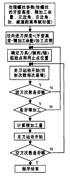
The block diagram of the thread processing program structure is shown in the following figure.
