
[Article Foreword] The author used the length of five articles to introduce the grinding process, grinding wheel and its dressing process and other related knowledge. In this article, the author will introduce some peripheral knowledge related to grinding.
01Analysis ideas for the problem of poor roundness
Although the characteristics of the grinding process itself determine that the size of the workpiece after grinding is relatively stable, there will also be size problems in the case of process changes or equipment failures.
The following table is an adjustment idea for engine crankshaft parts and grinding abnormal dimensions.
| Step | Check items | Standard |
| Step 1 | Analysis curve | Continuously process three pieces, measure Adcole, analyze the roundness curve state, if it is consistent and stable, perform roundness compensation on the workpiece, and confirm whether the roundness compensation is effective. |
| Step 2 | Check workpiece surface quality | Check whether there are ridge marks on the surface of the workpiece, especially the M2 main journal, because the center frame clamps the M2 main journal when machining other hosels, and the surface quality of the M2 main journal will affect the roundness of other hosels. Measure the first piece after the grinding wheel is trimmed. Roughness, ensure that the roughness is on the upper limit (spec: 0.8, the roughness of the first piece after trimming is required to be about 0.6). |
| Step 3 | Check the grinding wheel surface | There is no chipping on the surface of the grinding wheel, and the grinding wheel is trimmed. |
| Step 4 | Roundness compensation full clear | The roundness of the compensation is still bad after many times, and it is necessary to clear all the main journal and connecting rod journal roundness compensation (M5 generally does not change too much, it can be reserved for trial). Then, the fine grinding of the journal is removed during processing, and only the rough grinding is retained. The measured roundness of the first workpiece is generally large, and then only M2 is compensated for reprocessing, and the roundness of the second workpiece will decrease, but the trend on the graph should be the same as The first workpiece is the same. At this time, if the roundness of M2 is still large, it is necessary to continue to compensate once, and it is better to compensate the roundness of M2 to less than 3u. Then the workpiece is processed and finely ground, and the other main journals with larger roundness are compensated. After the main journal is OK, the connecting rod journals are compensated. |
| Step 5 | Check whether the workpiece interferes with the support | The gap between the workpiece and the support block is 0.3~0.5mm |
| Step 6 | Check Steady Rest Accuracy | There is no damage to the hard alloy block of the center frame, and the clamping accuracy of the center frame is as follows: the front top of the center frame is ≤ 0.003mm, and the upper top is ≤ 0.003mm; |
| Step 7 | Check the accuracy of the headstock and tailstock | Headstock accuracy standard: headstock top runout≤0.003, tailstock top runout≤0.003mm |
| Step 8 | Check the upper\side busbars | Clamp the master with two tops, check the upper busbar and side busbar, standard: upper busbar≤0.02mm, side busbar≤0.02mm |
| Step 9 | Check workpiece clamping force | Use the produced force sensor master to measure the workpiece clamping force, and adjust the position of the tailstock according to the size of the measured force. The force sensor is currently being calibrated |
| Step 10 | Check the floating amount of the hydrostatic guide rail | Measure the floating amount of the static pressure guide rail, standard: the floating amount > 0.015mm |
| Step 11 | Check the backlash of the X-axis hydrostatic guide | Shielded grating ruler, measure the backlash of the X-axis static pressure guide rail, standard: backlash≤0.002mm |
| Step 12 | Replace the grinding wheel | Replace the grinding wheel, refinish the grinding wheel |
| Step 13 | Check parameter settings | Check whether the workpiece correction parameter settings and speed setting parameters meet the requirements |
02Solutions and countermeasures for poor surface problems
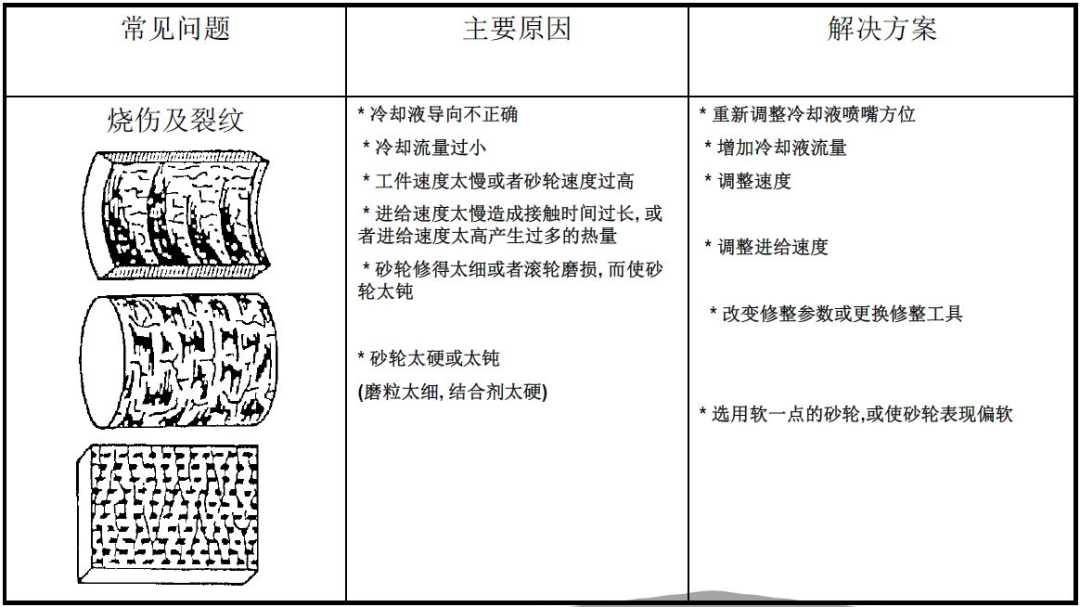


Knowledge Point 1 - Concept of Grinding Efficiency
The removal rate of the material can be expressed as the product of the average cross-sectional area of grinding, the average length of grinding and the number of abrasive grains involved in grinding per unit time.
Ways to improve grinding efficiency:
a. Use high-speed and ultra-high-speed and wide grinding wheels to increase the number of abrasive particles per unit time.
b. Use deep-cut grinding to increase the grinding length.
c. Use heavy-duty and other powerful grinding methods to increase the average cross-sectional area of grinding.
Knowledge point 2-grinding knife phenomenon
After the abrasive particles on the grinding wheel become dull, the radial resistance of grinding increases, which puts forward higher requirements on the rigidity of the equipment.
When cutting workpieces with high hardness, the poor rigidity of the machine tool can easily cause grinding vibration and accelerate the wear of abrasive particles of the grinding wheel.
After the abrasive particles on the grinding wheel become dull, the radial resistance of grinding increases, which puts forward higher requirements on the rigidity of the equipment.
If the rigidity of the machine tool is poor, it will cause the grinding wheel to "give the knife" when feeding and grinding. For example, the theoretical depth of cut is 0.2mm, and the actual material removal may be 0.15mm.
In addition, if the center is worn and the workpiece is on one circumference, the degree of "leaving the knife" is inconsistent, which is relatively random, which will cause the processed workpiece to have poor roundness/cylindricity.
Increasing the linear speed of the grinding wheel and reducing the depth of cut and traverse speed during grinding can reduce the grinding force and reduce the rigidity requirement of the grinding system.
Knowledge point 3 - black spot problem on the surface of grinding wheel
Possible cause 1 - pore former
When the grinding wheel is made, it is necessary to add various pore-forming agents; such as walnut powder, corn kernels, etc., when the grinding wheel is sintered, the temperature is as high as 1300 ° C, and the pore-forming agents are all gasified.
The black spot problem may be caused by the pore-forming agent not fully volatilized and remaining inside the grinding wheel.
Possible cause 2 - Debris deposition
The grinding wheel partially participates in grinding in the radial direction, and the grinding debris is not washed away by the coolant, but is deposited in the pores of the grinding wheel to form black spots.
Knowledge point 4 - grinding wheel hardness testing method
Grinding wheel hardness is tested by sandblasting method.
The specific method is to pass the standard specification of quartz sand (national standard) through the funnel-shaped container and inject a certain air pressure to eject.
Dimples are formed on the surface of the grinding wheel; by measuring the depth of the dimples, the hardness of the grinding wheel is determined.
Knowledge Point 5 - Grinding Coolant
Coolants are oil-based and water-based.
Both have advantages and disadvantages.
A. The surface finish of the workpiece processed by the oil-based coolant is good, but due to the high viscosity of the oil-based coolant, it is easy to fill the grinding wheel with abrasive debris or invalid sand, causing the grinding wheel to be stuck.
B. Water-based coolant has no grinding wheel sticking problem, but water-based coolant is easy to rust the workpiece.
Knowledge point 6-grinding wheel uses the maximum linear speed
A. Generally, the grinding wheel manufacturers will give the maximum linear speed of the grinding wheel. This linear speed is the linear speed after considering the safety factor (usually 1.6); if the grinding wheel exceeds this linear speed, it is easy to be broken when used, which will damage the equipment.
B. If the grinding wheel with poor quality is used for a long time, it will affect the precision retention of the grinding machine; because the poor grinding wheel has high requirements on the grinding process, coolant, and rigidity of the machine tool.
C. The method of judging whether the grinding wheel has cracks: lightly tap the grinding wheel with a small hammer, the sound of a good grinding wheel is crisp; the sound of a grinding wheel with cracks is dull, commonly known as "dumb sound".
Knowledge point 7 - knowledge of polishing and polishing tape
Polishing refers to the use of mechanical, chemical or electrochemical action to reduce the surface roughness of the workpiece to obtain a bright and smooth surface. It is the modification of the surface of the workpiece by using polishing tools and abrasive particles or other polishing media.
Polishing does not improve the dimensional accuracy or geometric accuracy of the workpiece, but aims to obtain a smooth surface or specular gloss, and sometimes it is also used to eliminate gloss (matting).
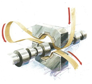
The surface polishing of passenger axle parts mainly uses polishing tape. The working principle is shown in the figure above. Common brands include 3M, Hermes and FUJISTAR.
The polishing belt is a precision grinding tool, and its grinding principle is the same as that of the resin grinding wheel. Its structure is as follows:
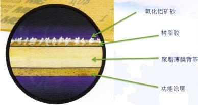
The author has used 3M brand 373L specification and 272L specification. The situation is compared as follows:
373 Series Polishing Belts | 272 Series Polishing Belts | |
| Origin | U.S. | U.K. |
| Price | / | About 2 times more than 373 series polishing belt |
Functional coating | Anti-slip coating | Uncoated |
Abrasives | AL2O3 ore sand | AL2O3 ore sand |
Back base material | Mylar | Mylar |
Binders | Resin adhesive | Resin adhesive |
Composition 1 Alumina Ore Sand
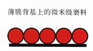
The main material of ore sand is micron-scale alumina, and its particle diameter determines the efficiency and roughness of grinding. The mineral sand is attached to the film backing by electrostatic sand planting technology. The diameter of abrasives ranges from 9 to 100u.
The larger the diameter, the higher the metal removal efficiency and the greater the roughness.
Its normal arrangement is as follows:
Composition 2 Mylar Backing
There are usually three types of backing materials: thick paper base, cloth base, and polyester film backing. Its microstructure is as follows:
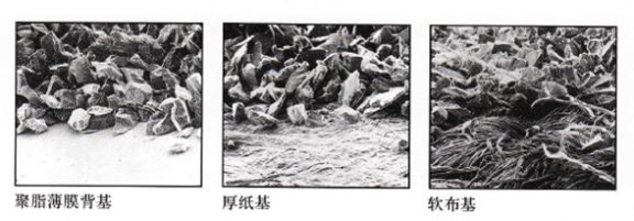
The cost of the film backing is high, and it is mainly used for precision processing, which solves the problem that thick paper and cloth can not withstand high tension. Moreover, the deformation of the film backing is small, which can ensure better consistency of the machined surface.
Composition 3
Functional coating/resin glue
Functional coating
The coating is behind the backing and does not participate in processing. It is mainly used to control the friction coefficient when the polishing belt is in contact with the polishing stone, usually adding a non-slip coating.
According to the different grinding fluids in the processing environment, other anti-corrosion or anti-chemical reaction coatings can also be appropriately added.
resin glue
Resin glue is used to fix the ore sand, and cooperates with the electrostatic sand planting technology to ensure the even distribution of the ore sand.
The principle of electrostatic sand planting is to make the abrasive become a charged body through a high-voltage electrostatic field, which is adsorbed on the backing coated with resin glue. Since the action point of the electric field acts on the center of the sand grain, it is possible to make the big end of the sand grain face the resin glue and the small end (ie the sharp end) to face outward.
Moreover, by controlling the voltage and current of the electrostatic field, the electric field force can be controlled, thereby controlling the particle size of the gravel more effectively.