Thanks to the readers for waiting for several days, the next part of the drill life prediction formula arrives as scheduled.
In the last article, the author introduced the background of drilling and drill bit application, and combined with his own work case, explained the process of improving the life of the crankshaft drill bit, and completed the first step, locking the main cause of wear, that is, the wear of the drill tip.
In this article, the author will select the form of the life prediction formula and quantitative experimental indicators for the wear of the drill tip, and on this basis, carry out the experimental design and the calculation of the regression equation, and then predict the life of the drill bit based on this.
1. Life prediction formula
In practical applications, in addition to observing the wear profile of the drill bit, there are two common methods to measure whether the life setting of the drill bit is reasonable.
One is to consider the sum of the depths of the holes machined during the life of the drill (referred to as the total depth).
The other is to take into account the distance the drill angle traverses over the tool life (referred to as the total distance).
The former is easy to calculate, and it can be calculated by multiplying the number of pieces by the hole depth, but the influence of cutting speed and feed on tool life is not considered; the latter, although the cutting speed and feed are considered in the calculation, it is still impossible to quantify the change of cutting parameters. impact on tool life. We plan to vary cutting parameters, track changes in tool life, and use this to establish a drill life formula.
According to the classical cutting theory, the factors that have the greatest impact on tool life are cutting speed, feed and depth of cut. In drilling, the depth of cut is determined by the cutting speed and the feed, and the drill tool life formula only needs to consider the cutting speed and the feed as variables, as shown below:

In order to facilitate the calculation, we transform the equation into:

Among them, we select the distance across the shoulder of the drill (unit m) as the tool life index, which is represented by T; the linear speed of the shoulder of the drill (unit m/min) is selected as the cutting speed, which is represented by V; the feed rate (unit is mm) /min) is represented by F.
2. Experimental design scheme
The crankshaft production line dynamic balance station is to drill a series of balance holes with different angles (phases) and depths (balance amount) on the crankshaft blades to meet the crankshaft dynamic balance requirements.
In order to accurately control the depth of the balanced hole, the device monitors the axial force of the drill bit during the drilling process in real time. This function also plays a role in monitoring the wear of the tool. When the axial force exceeds the set alarm value, it will prompt for replacement. tool, and displays the total depth of holes machined over the life of the tool.
The balanced hole drill bit not only has a constant tool wear standard, but also can accurately record the service life (total depth) of the experimental drill bit. Therefore, we choose it as the experimental tool, and combine the use practice to set the alarm value of the drilling axial force. is 5500N.
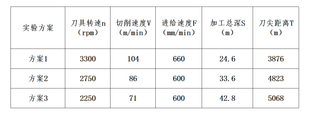
According to the equipment processing cycle and tool usage, we set the experimental plan:
Rotating speed
Gradually reduced from 3300 rpm to 2750 rpm and 2250 rpm
Feed rate
Reduced from 660mm/min to 600mm/min
The plan is as follows:

Table - Experimental Protocol and Results
There are three experimental results, and the following three equations can be obtained:
Equation 1

Equation 2

Equation 3

For convenience, define:
A2=lnT1-lnT2; A3=lnT1-lnT3; B2=lnV1-lnV2; B3=lnV1-lnV3; C2=lnF1-lnF2; C3=lnF1-lnF3, then
Feed index c=(A2B3-A3B2)/(C2B3-C3B2)
Speed index b=(A2-C2*c)/B2
Formula coefficient a=lnT1-b*V1-c*f1
After substituting the experimental data, a=3959619943b=-0.20209c=-1.98728, so the tool life formula should be:

3. Promotion and application of formulas
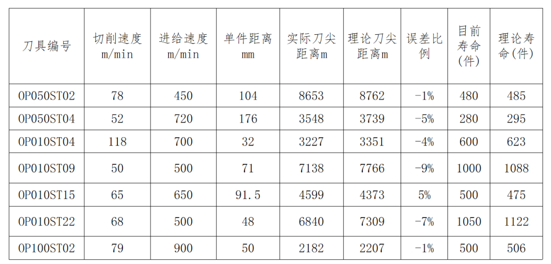
Since only three sets of representative tool data are needed (if the service life exceeds the set tool life, the hole diameter will be too large), the life prediction formula of the drill tool on the same production line can be calculated, so this method has a strong promotion.
Taking other tools on the crankshaft as an example, by substituting the cutting parameters into the above formula, we can calculate the theoretical tool nose distance, and calculate its theoretical life according to the machining depth of a single piece.
As shown in the table below, the theoretical and actual life of most tools are not much different, so it can be seen that the tool life is still very accurate within a certain range.

4. Limitations of formula application
In the promotion process, it was found that the formula has a large deviation in the prediction results for large aspect ratio and large diameter drill bits. A large aspect ratio tool generally refers to a tool with a length to diameter ratio greater than 12, such as a crankshaft oil passage hole drill.
Due to the large aspect ratio and insufficient rigidity, it is more sensitive to the oscillation during the drilling process. In addition, the long drilling time and poor chip removal effect cause the cutting edge to burn after the accumulated cutting heat, so the predicted life is higher than the actual life.
Large-diameter drills usually refer to drills with a diameter greater than 12mm, such as drills for drilling the center hole of the crankshaft flange end.
5. Summary of application practice
1. When carbide drills process ductile iron, the main wear form is drill tip wear, and the common failure form after drill tip wear is too large aperture or exit burr, and severe tool breakage or chipping.
2. The wear degree of drill tip can be monitored by detecting the axial force of drilling. The recommended limit value of axial force is 5500N when machining QT600 ductile iron crankshaft.
3. The drill bit life prediction formula is, this formula is suitable for drill bits used in most crankshaft production lines, but for drill bits with an aspect ratio of 12 or more and a diameter of 12mm or more, the prediction error is large.
4. On the basis of this article, on the one hand, through design experiments, quantitatively explore the influence of drill tip (chisel edge) grinding size on tool life (axial force), on the other hand, will expand the study of drilling of aluminum and gray cast iron performance.
【Summary of the article】
Observing the wear profile and gradually increasing the tool life is a traditional method for process engineers to improve the tool life. The only difference lies in how to choose the target point for improvement, whether to gradually explore according to the arithmetic sequence, or to use theoretical calculations.
However, with the continuous development of sensor measurement and control technology, the online tool monitoring method has become more and more mature. At present, a variety of cutting monitoring systems have been applied in practice.
Based on the cutting process data collected by online monitoring, and using mathematical methods for processing and analysis, the accuracy of the prediction formula can be improved. Readers who are interested in cutting monitoring technology can leave a message for discussion.