There are many ways to make holes. Common ones are: drilling, reaming, reaming, boring, pulling, grinding, honing and grinding. If you count special processing methods, there are new technologies such as EDM, ultrasonic, and laser processing.
The most common is the machining of holes on lathes, drilling and boring machines. Let's start with the simplest and most common process in holemaking: drilling.
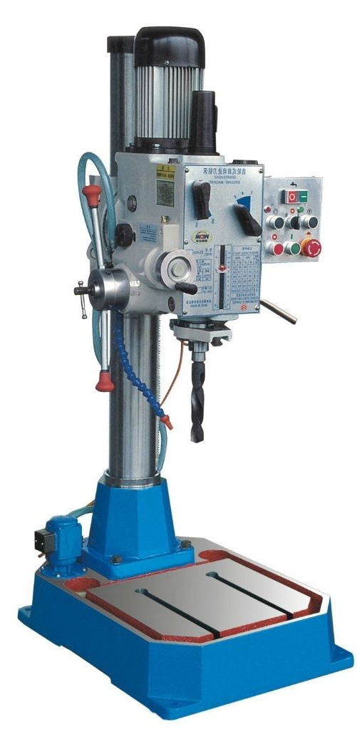
Drilling is a basic method of hole making. Drilling is carried out on drilling machines and lathes, and can also be carried out on boring machines or milling machines.
Commonly used drilling machines are desktop drilling machines, vertical drilling machines and radial drilling machines.
1. Twist drill
A twist drill is a standard tool for double-edged, drilling or reaming with complex shapes. It is generally used for rough machining of holes (accuracy below IT11 and surface roughness Ra6.3~25um), and can also be used for prefabricated holes for tapping, reaming, pulling, boring and grinding.
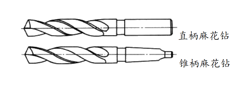
According to different clamping methods, twist drills are divided into straight shank twist drills and tapered shank twist drills.
2. Center drill
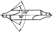
The center drill was first used in lathes, and it was used to punch the center hole of shaft parts. With the increasing popularity of automation, it is more and more widely used in multi-functional numerical control equipment.
Its biggest function is to drill the center hole to ensure the position of the part hole processing.
For processing features with high centering requirements, such as shaft center holes with large aspect ratios, direct use of twist drills will cause workpiece deformation due to excessive cutting force. At this time, special center drills are usually used. Specially designed center drills The drill point feature, which enhances the centering performance of the drill during machining, plus does not need to complete the entire section but only needs to machine the entry, usually 2 to 3 times the depth of the diameter.
3. Reaming drill
Compared with the twist drill, the reaming drill lacks the feature of the drill tip, so it can only be reamed after the twist drill or the center drill.

4. Flat drill:
For flat drills, the cutting part is ground into a flat body, the main cutting edge is ground to form a sharp angle, a relief angle and a chisel edge; the secondary cutting edge is ground to a relief angle and a secondary declination to control the diameter of the drill hole.
According to the manufacturing method, flat drills can be divided into integral type and assembled type.
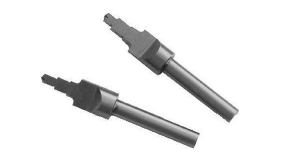
Integral flat drill: It is mainly used for the size range of diameter below 12mm. The material of its cutting part can be high-speed steel or cemented carbide. In the drilling of micro-holes of 0.03-0.5mm, the overall flat drill is still widely used.

Assembled flat drill: As shown in the figure above, it is mainly used for drilling or reaming in a large size range of 25 to 500 mm in diameter. Its structure consists of two parts: a drill pipe and a replaceable blade. The material of the replaceable blade is high speed steel or cemented carbide.
The disadvantages of flat drills are poor cutting conditions, low productivity, difficulty in chip removal, difficulty in maintaining the hole position when drilling, and low machining accuracy. The advantages are that the strength and rigidity are good, the structure is simple, the manufacturing cost is low, and the machine clip structure is easy to use.
5. Countersink:
A countersink is a countersink. Also called chamfering knife, chamfering drill, pocket drill, chamfering tool, a drill for countersinking conical countersinks.
The hole can be deburred, chamfered, and countersunk. The premise is that there must be a guide hole before subsequent processing, and the upper and lower conical holes. To place a taper flat head screw, it is necessary to machine a countersunk hole and a taper hole. Orifice trimming and deburring is to lightly trim the edge of the orifice and remove the edges and corners of the orifice.

Main motion: the rotary motion of the drill bit (drilling machine), or the rotary motion of the workpiece (lathe).
Feeding movement: the drill bit performs linear feed movement along the axis (drilling machine), or the workpiece performs linear feed movement along the axis of the drill bit (lathe).
Finally, we will summarize the main parameters of the drilling process and their calculation formulas. In order to let everyone understand the meaning of the parameters, the author will explain the meaning behind these parameters in combination with the failure mode of the drill bit.
01 Cutting speed
Refers to the linear velocity at the outer edge of the main cutting edge of the drill.

The outer edge of the main cutting edge, which is often referred to as the "drill angle", is the position where the drill bit has the largest diameter and the highest linear speed.
When the line speed is too high, the severely worn drill corner will lead to the deterioration of the hole wall roughness, for example, the hole wall will be scratched due to the sticky chips of the drill corner. Moreover, the worn drill angle will cause the cutting force to increase, resulting in flanging burrs when machining the outlet end.
02 Feed f, af, vf
Feed per revolution f (mm/r): The axial relative displacement between the drill bit or workpiece per revolution.
Feed per tooth af (mm/z): The relative displacement between the drill bit or workpiece relative to the drill bit when one tooth rotates.
Feed rate Vf: The axial relative displacement of the drill or workpiece per minute.
The classic cutting theory holds that cutting speed is the primary factor affecting tool life, but drills whose main function is drilling is particularly sensitive to feed.
This is because the "chisel edge" in the drill tip feature is an important factor in determining the centering performance of the drill.
Since the "chisel edge" is located at the center of rotation of the drill bit, the linear speed is zero, but it needs to be advanced in the feed direction like a "chisel". Therefore, when the feed rate is too large, the wear of the drill tip is accelerated and the drill bit The centering performance is degraded, affecting the straightness or position of the hole.
03 Back cut amount (drilling depth) ap
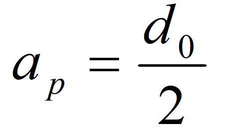
The amount of back engagement determines the load on the cutting edge. When the amount of back engagement is too large, the problem of chip fusion will be aggravated. Since the diameter of the drill bit is fixed, reducing the amount of back-engagement requires adjusting the size of the previous tool.
04 Cutting thickness and width
The cutting thickness ac is the thickness of the cutting layer measured in the basal plane perpendicular to the direction of the main cutting edge.

Cutting width aw The width of the cutting layer measured along the main cutting edge.

Cutting thickness and width are important parameters that affect chip shape and chip breaking.
05 Cutting area Acz, Ac
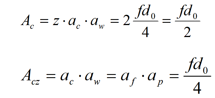
Cutting area is an important parameter for calculating drilling power.
Due to space limitations, in this article, the author introduces the basic definition of drilling and the types and basic parameters of common drill bits.
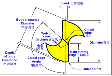
Attentive readers may have found that the author mentioned the characteristics of the drill tip many times in the article, but did not introduce the characteristics and functions of each part of the drill bit in detail. Please don't worry. A pit: Leave a feature map of the drill tip.
