
Article Summary
In the previous article "Cleanliness Issues, Burr Issue Background", we successively introduced the definition, hazards, and formation and removal methods of burr issues.
Readers who pay attention to the public account will definitely remember that there is an article "The nemesis of milling burr: "Pull Milling Cutter"", the introduction is to optimize the tool arrangement structure, allocate the machining allowance of each blade, reduce the cutting edge Mouth load, protect the cutting edge, reduce the cutting force, and suppress the flanging burr problem.
In this article, we will introduce the EOS theory for deburring in milling.
1. Classification of milling burrs
The most common milling processes in engineering applications can be summarized as slot milling and step milling, and both of these milling methods can almost cover the burr-forming features of other milling processes. Although the burr is only generated when the tool is out of the tool during cutting, the milling process is a more complex type of cutting process. During the machining process, the cutting edge is constantly changing, and the entry and exit of the blade are changed at any time, so the burrs generated are also more complex. , according to the position of the workpiece in the slot milling process can be divided into 8 categories. as the picture shows.
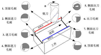
The formation mechanism of burr at different positions is different, and its size is also inconsistent. Generally, for slot milling, the feed burr is the smallest, and the feed burr on the side of the workpiece is the smallest, followed by the feed burr on the side of the up-milling side, the burr on the side of the up-milling side, the top burr on the down-milling and up-milling edges, and the up-cut milling. The edge and side exit positions (6 and 5 in the figure above, respectively) have the largest burr size.
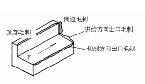
The rest of the milling, such as face milling, step milling can also be divided according to the above. According to the division of the machining direction, burrs can be divided into top burrs, side burrs, burrs in the feeding direction and burrs in the cutting direction, as shown in the figure below, of which the exit burrs in the feeding direction are the largest in size.
2. Introduction to EOS Theory
According to the burr formation mechanism, the burr is produced at the edge where the material to be processed is extruded. The direction in which the material being processed is extruded depends on the feed direction, blade geometry, and workpiece edge position. The EOS (Exit Order Sequence) of the three points A, B and C on the insert when the tool leaves the edge of the workpiece determines the size of the burr, as shown in the figure below, that is, the direction of the cuttingedgewhen the tool leaves the edge of the workpiece Determining the size of the glitch is the famous EOS principle.
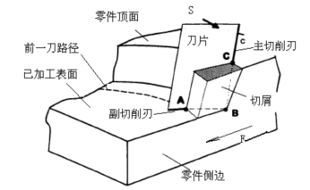
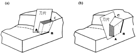
When the tool leaves the workpiece, there are 6 combinations of EOS in the order that the point on the cutting edge leaves the workpiece, ABC, BAC, ACB, BCA, CAB, CBA. Through scientific experimental verification, it is known that the burrs generated by EOS in the order of ABC-BAC-ACB-BCA-CAB-CBA gradually increase.
That is to say, from the perspective of burr control, the geometry of the blade and the processing conditions we selected should make the EOS in the processing process conform to the order of ABC, as shown in the figure below.
For the exit burr in the cutting direction, there are two main factors that affect the EOS:
1. The geometry of the blade itself
2. The position of Exit point relative to the tool center during machining
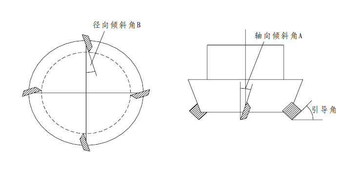
Taking a disc milling cutter as an example, the geometry of the cutting edge is shown in the figure above: the main factors affecting EOS are the axial inclination angle A and the radial inclination angle B. The best angle combination for A and B is experimentally studied as A-B is (-6°, 6°). This angle combination has the best comprehensive performance and is most suitable for actual machining. The burr produced by it is generally small, and the processed material is easy to obtain a better finish, and the tool has good wear resistance. If A-B selects the combination of (-6°, -6°), although the burr height is smaller, the surface finish is extremely poor, and the tool wear is also very severe. For the exit burr in the cutting direction, the position of the tool center relative to the edge of the part during machining is also an important factor affecting EOS.
3. Practical application cases
At work, the author encountered a flanging on the edge of the part after milling the plane of an aluminum part with a PCD disc milling cutter
In the case of burrs that cannot be removed by the brush, the following attempts were made:
1. Brush related optimization
Improve the rigidity of the brush
With the cooperation of the brush manufacturer, not only the diameter of the bristles is enlarged, but also the rigidity of the brush is increased by adding glue and bundling.
Optimize brush rotation and trajectory
In the original process, in order to facilitate programming and consider the integrity of the track coverage, the rotation direction and tool path of the brush are the same as those of the milling cutter. After the burr appeared, the author changed the rotation direction of the brush and the path of the tool to be completely opposite to that of the milling cutter according to the characteristics of the burr appearing at the milling cutter position.
Optimized brush down pressure and compensation
The initial downward pressure of the brush refers to the re-feeding distance after the top of the brush contacts the workpiece. When a nylon brush is used for aluminum processing, it is usually 3-5mm. The greater the downward pressure, the better the cleaning effect.
The compensation amount of the brush refers to the compensation of the downward pressure of the brush according to the wear condition of the brush set in the program. There are usually two ways. One is uniform compensation, that is, after processing a fixed set amount, the brush is lowered. The pressure is used to compensate for a fixed distance. Another more reasonable way is to compensate according to the use of the brush. At the beginning of the use of the brush, the bristles are long and the rigidity is poor, and the compensation amount is too large. Strong rigidity and small compensation amount.
In order to improve the cleaning effect of the brush, the author increased the initial pressing amount by 100% and reduced the compensation interval by 30%.
Combining the above countermeasures, the generation of burrs has been suppressed to a large extent. It can be seen that the brush is a very effective countermeasure for removing burrs. When arranging the processing technology, appropriate consideration should be given to adding brush cleaning after processing key features.
2. Change of cutting parameters and allowance
According to the above theory, the mechanism of burr generation is that the edge of the cut area is insufficiently supported, and the material to be cut is not completely removed, that is, before being sheared and fractured, plastic deformation occurs first, and then remains on the edge of the workpiece.
To sum up, the purpose of optimizing cutting parameters and allowances is twofold, namely reducing cutting force and reducing complete deformation, as shown in the figure below.

First of all, the author exploratively reduced the cutting speed by 50%, because reducing the cutting speed can not only reduce the cutting force, but also reduce the cutting temperature, reduce the softening of the workpiece material, and increase the hardness of the material to be cut. But the improvement effect is not obvious.
【For the reason of failure】
The author believes that the reduction of cutting force and cutting heat caused by the reduction of cutting speed may be insufficient to improve the support of the material to be cut. Subsequently, the author tried to divide the original cutting allowance into two completions, and the machining depth when the final surface was about to be formed was reduced by 50%. The purpose of this move is to improve the support performance of the material being cut. However, during the experiment, machining chatter marks appeared and failed.
In view of the reasons for the failure, the author believes that the influence of cutting depth is slightly greater than that of cutting speed for the cutting force during aluminum machining, and when the cutting force is reduced, the vibration of the process system produces vibration marks on the surface of the workpiece. To sum up, the optimization effect of cutting parameters and allowances is limited, and the original settings can be restored by canceling the changes.
3. Tool angle optimization
Based on the EOS theory, the rake angle of the tool side tooth is changed to -6°, and the rake angle of the end tooth is changed to +6°.
In order to verify the effect of the tool scheme, the optimization related to the brush is cancelled. Before the tool change, the burr appeared during the first 30%-50% of the tool life, and after it was higher, the burr appeared after 80% of the tool life, and the use effect was remarkable.
Due to the urgency of production, the author cannot try other angle combinations. Interested readers can optimize the angle size to further reduce the cutting force and achieve better burr removal effect.
chapter summary
This paper introduces the EOS theory of suppressing the milling burr problem, and combines the author's application case to introduce the common methods for solving the milling burr problem of aluminum parts. The author will summarize the theories and methods for solving the burr problem in the drilling process in the follow-up, so stay tuned!